Autonomous human transport
{{CODE1}}
The reason for me starting this project is to create a fully autonomous quadcopter that can transport people without any human intervention. In order to be useful for the common public it should fly without requiring a human pilot.
 |
 |
 |
Want to quickly jump to a chapter?
Introduction
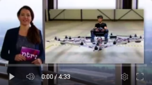
Imagine a customer that calls the quadcopter, takes a seat and enters his desired destination. Without any human intervention the system will takeoff and arrive quickly at the given destination.Before I started this project I gained some experience during my work at a company that produced Unmanned Aerial Systems (UAS). However I am a firmware engineer and to realize my vision I had dive into unfamiliar disciplines like mechanical stress calculations and circuit design. Throughout the process there were a lot of uncertainties and I learned that knowing is only part of what is needed to realize my goal. I stared working on small prototypes in order to get a feeling for the involved technologies.
![]() After building several small prototypes, I focused on questions like; how much electrical power do I need? What type of propellers are appropriate? What materials should I use for the frame? Where can I find a place to test? And many, many more…
After building several small prototypes, I focused on questions like; how much electrical power do I need? What type of propellers are appropriate? What materials should I use for the frame? Where can I find a place to test? And many, many more…
Engine thrust
So how much thrust is required? There should be enough thrust to lift the quadcopter itself with extra payload (being the person). As a basic estimate I took, 55 Lbs frame, 55 Lbs electrical components plus batteries and 132 Lbs payload. This means that we should have enough thrust to lift 243 Lbs. There are many formulas that calculate static thrust. Equation 1 relates static thrust in pounds with propeller speed and diameter in inch . Equations 2 defines the power in Watts that is required to generate that thrust. In addition the propeller pitch in inch is required.
 |
(1) |
 |
(2) |
The thrust 

 |
(3) |
To determine how many RPM the engine can generate we have to look at the propeller design. It has a diameter of 20 inch and pitch of 13 inch.
 |
(4) |
Now we need to have a look at the power rating of the engine, which is 3kW. Using equation 2 we can calculate the RPM at 3kW.
  |
(5) |
Lets define the maximum RPM at 3kW 
 |
(6) |
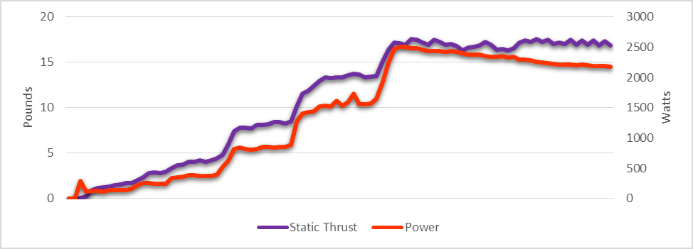
So 20 engines will generate 387 pounds of static thrust which should sufficient (e.g. > 243). In order to verify these calculations I created an engine test stand.
To measure the generated static thrust I used a loadcell that was connected to my computer via a micro-controller. The controller communicates with the loadcell, power monitoring device and engine controller. I performed various tests to determine how much static thrust the engine could generate, here are some results.
 As a power source for the quadcopter I choose electricity. To be more specific I used lithium-ion polymer (LiPo) cells. The advantage of electricity is that I do not have to bother with fuel. LiPo cells also have a good weight to power ration and can provide large amounts of power in bursts. A disadvantage however is the amount of total power it can deliver. Gas power systems usually can operate much longer than electrical systems. Also care should be taken when using LiPo cells. The voltage they deliver range from 3.6-4.2v and should never go outside these limits. An underpowered cell can get permanently damaged and more serious, an overpowered cell can explode. To prevent this a voltage monitoring system should be used to watch and handle the voltage.
Based on the number of cells and required power we can estimate the expected flight time. For each engine I used a battery pack of 10 LiPo cells. The battery produces 42v (e.g. 4.2v per cell) and was rated to deliver 2.2Ah (thus it can provide 2.2A for one hour before its empty). Furthermore the battery has a discharge rating of 45C. The discharge rating specifies the maximum amount of current that can be delivered by the battery and is defined in equation 7 . The time it can operate before running being empty is show in equation 8. With Maximum current the battery can deliver in amperes 


 |
(7) |
 |
(8) |
If the engines would consume the largest amount of ampere that the battery could provide 


 |
(9) |
At 42v an engine 3.3kW consumes 

![T = ({\sqrt[3]{{42 \cdot I}\over{20^4 \cdot 13 \cdot 5 \times 10^{-15}}}})^2 \cdot 20^4 \cdot 2.7734 \times 10^{-12}](http://l.wordpress.com/latex.php?latex=T%20%3D%20%28%7B%5Csqrt%5B3%5D%7B%7B42%20%5Ccdot%20I%7D%5Cover%7B20%5E4%20%5Ccdot%2013%20%5Ccdot%205%20%5Ctimes%2010%5E%7B-15%7D%7D%7D%7D%29%5E2%20%5Ccdot%2020%5E4%20%5Ccdot%202.7734%20%5Ctimes%2010%5E%7B-12%7D&bg=FFFFFF&fg=000000&s=0 "T = ({\sqrt[3]{{42 \cdot I}\over{20^4 \cdot 13 \cdot 5 \times 10^{-15}}}})^2 \cdot 20^4 \cdot 2.7734 \times 10^{-12}") |
(10) |
We can visualize the operational time of a single engine against the thrust that is generated using equation 10 and 8.
Frame design
For the quad copter frame design I was looking for someone who had experience in mechanical design. I found someone who good experience in metallurgy and together we prototyped a frame that was strong, yet light enough to lift people. In the following section I will briefly describe some basic terminology that is required to perform structural analysis.
All materials have a strength values the represents the toughness. The yield strength represents the maximum stress at which the material will not return to its origin shape or length after removing the load. So if we would put a very heavy object on a beam it will bend, at that moment we exceed the yield strength, because the beam will be bended after removing the object. The ultimate (tensile) strength is the maximum stress a material endures without breaking. The involved forces can be represented in many ways. For calculations I used pound per square inch (psi). In addition to toughness all materials have a mass, which we will represent in pound per cubic foot 


| Material | Yield strength (psi) | Ultimate strength (psi) | Density (lb/ft³) |
| Steel (1090) | 35824 | 121977 | 473 |
| Steel (2800) | 379564 | 390587 | 499 |
| Aluminum alloy (2014-T6) | 60046 | 70053 | 175 |
| Aluminum alloy (6060-T6) | 10000-26000 | 20000-33000 | 169 |
| Copper | 10153 | 31908 | 557 |
| Diamond | 232060 | 406106 | 218 |
| Carbon nanotube | N/A | 1595415-9137377 | 2-84 |
Calculating all the involved forces can be quite cumbersome, these days we fortunately don’t have to do that. In order to validate the design I used a structural analysis tool.
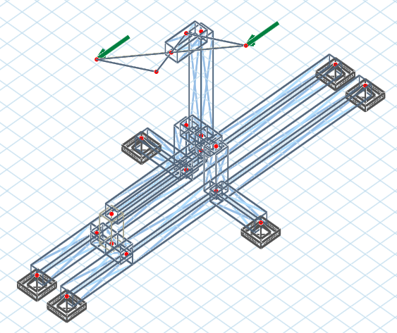
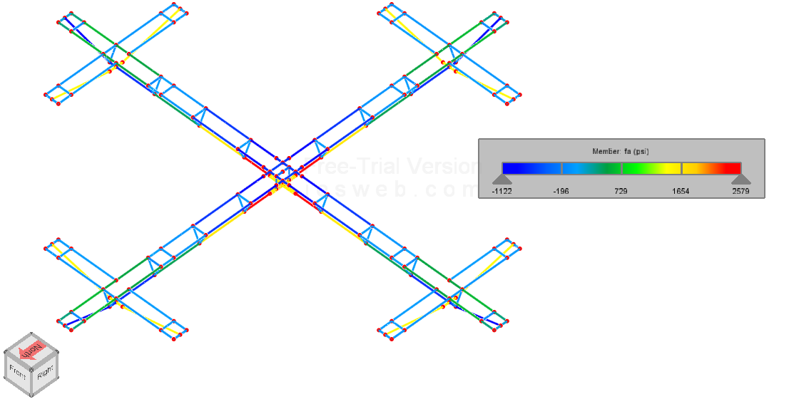 The simulated frame was designed using aluminum alloy type 6060 furthermore 243 Lbs of load was applied in the center. The resulting stress is color-coded, blue for compression and red for expansion. It is important not to exceed 10 ksi as this would surpass the yield strength and permanently deform the frame. Also more than 20 ksi will cause the frame to break, which is of course unacceptable. In the simulation stress never exceeds 2.1 ksi, which is tolerable.
Control system
As control system I used the well-known MultiWii Autopilot. Among others it takes care of the quad copter stabilization. Without a controller the quad copter would flip over and not be able to fly. One of the most common control system implementations is a proportional integral derivative (PID) controller. It is one of the most easy to understand and widely used controllers that receives signals from the system it controls and is known as a closed-loop controller. In our situation sensors provide information about the orientation if the quadcopter. The error is defined based on the difference between the computed orientation and desired orientation (e.g. setpoint). The output to the engines is adapted proportional to the error in order to stabilize the quadcopter.
GainKp: Ki: Kd: noise |
|---|
The PID controller has three terms; proportional (


 / {\Delta_t}}")

The P-I-D values are combined with three preset gain terms. We have the proportional gain (


Power management
The main responsibility of the power management system (PMS) is to manage the LiPo batteries. It connects to a 220VAC outlet and is capable of charging and also discharge all batteries. The discharge functionality is used to reduce the effect of battery capacity degradation that occurs overtime. The state of charge (SoC) is a well-known property of a battery that describes its charge state (analog to a car’s fuel tank). Lithium batteries that are stored when they are fully charged (thus at 100% state of charge) will degrade much faster. In order to lengthen their lifetime and counter capacity degradation we should store them at roughly 40% state of charge.
When activated the PMS will discharge all batteries to 40% SoC. In preparation for a flight the PMS can also be activated to charge the LiPo batteries. When charging; the system takes care of balancing the LiPo cells and assures that they never exceed the 4.2v limit.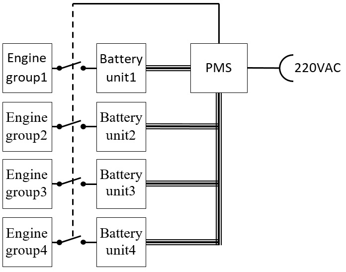 The quadcopter has 4 battery units. In order to minimize the power passing through each cable every unit is connected to a separate set of engines. When the PMS is connected to 220VAC it automatically disconnects all batteries from the engines and starts charging.